Jika pada artikel sebelumnya sudah saya bahas bagaimana mengakses EEPROM internal, dalam beberapa kasus jumlah atau kapasitas 256 byte tidaklah cukup. Jangan kawatir, masih ada EEPROM lain, yang tentunya bukan internal, yang kapasitasnya lebih dari 256 byte.
Pembahasan EEPROM eksternal saya awali dengan memperkenalkan sebuah EEPROM AT24C1024 dari Atmel dengan kapasitas 1024 byte atau 1KByte, lumayan bisa menyimpan data 4 kali lipat dari EEPROM internal-nya PIC16F877. Namun yang lebih penting adalah antarmukanya menggunakan I2C, jadi sekalian belajar bagaimana membuat rangkaian dasar I2C dan membuat programnya sekaligus.
I2C (“i-squared cee” or “i-two cee”; Inter-Integrated Circuit; generically referred to as “two-wire interface”) is a multi-master serial single-ended computer bus invented by Philips that is used to attach low-speed peripherals to a motherboard, embedded system, cellphone, or other electronic device. Since the mid 1990s, several competitors (e.g. Siemens AG (later Infineon Technologies AG), NEC, Texas Instruments, STMicroelectronics (formerly SGS-Thomson), Motorola (later Freescale), Intersil, etc.) brought I2C products on the market, which are fully compatible with the NXP (formerly Philips’s semiconductor division) I2C-system. As of October 10, 2006, no licensing fees are required to implement the I2C protocol. However, fees are still required to obtain I2C slave addresses allocated by NXP. (wikipedia)
Pada Gambar 1 ditunjukkan contoh rangkaian antarmuka I2C dengan sebuah master (mikrokontroler), tiga slave (ADC, DAC dan mikrokontroler lainnya) dan (tidak lupa) dua buah resistor pull-up yang masing-masing ditempatkan pada kaki SCL dan SDA. Pada Gambar 2 ditunjukkan contoh IC AT24C1024.

Gambar 1
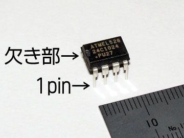
Gambar 2
Deskripsi AT24C1024
The AT24C1024 provides 1,048,576 bits of serial electrically erasable and programmable read only memory (EEPROM) organized as 131,072 words of 8 bits each. The device’s cascadable feature allows up to two devices to share a common two-wire bus. The device is optimized for use in many industrial and commercial applications where low-power and low-voltage operation are essential. The devices are available in space-saving 8-lead PDIP, 8-lead EIAJ SOIC, 8-lead Leadless Array (LAP) and 8-lead SAP packages. In addition, the entire family is available in 2.7V (2.7V to 5.5V) versions. (datasheet)
Fitur AT24C1024
- Low-voltage Operation: 2.7 (VCC = 2.7V to 5.5V)
- Internally Organized 131,072 x 8
- Two-wire Serial Interface
- Bidirectional Data Transfer Protocol
- Write Protect Pin for Hardware and Software Data Protection
- 256-byte Page Write Mode (Partial Page Writes Allowed)
- Random and Sequential Read Modes
- Self-timed Write Cycle (5 ms Typical)
- High Reliability
- Endurance: 100,000 Write Cycles/Page
- Data Retention: 40 Years